And here's the spiel:
Breadboard Power Supply 5V/3.3V
PRT-00114
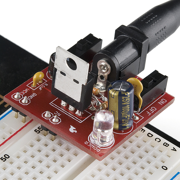
Description: Here is a very simple breadboard power supply kit
that takes power from a DC wall wart and outputs a selectable 5V or 3.3V
regulated voltage. The .1" headers are mounted on the bottom of the PCB
for simple insertion into a breadboard. Pins labeled VCC and GND plug
directly into the power lines. The lone pair of pins have no electrical
connection but help support the PCB.There are two pins available within the barrel jack footprint. Any stripped +/- DC supply can be connected instead of the barrel connector. Board has both an On/Off switch and a voltage select switch (3.3V/5V).
Comes as a bag of parts kit and is easily assembled if you can follow the silkscreen indicators and have beginning experience with a soldering iron. You will need to read the resistor bands or use a multimeter to determine the resistor sizes.
Dimensions: 1.25x1.25"
Kit Includes:
- DC Barrel Connector (2.1mm center positive)
- TO-220 Voltage Regulator (LM317 1.5A max current)
- 1N4004 Reverse Protection Diode
- 100uF 25V Capacitor
- 10uF 25V Capacitor
- 0.1uF 50V Capacitor
- Red Power LED - High Brightness
- 2 x SPDT Slide Switch
- 4 x 0.1" Header Pins
- 2 x 330 Resistor 1/6W
- 390 Resistor 1/6W
- 240 Resistor 1/6W
- Bare PCB with Silkscreen Indicators
- PTC resettable fuse
The soldering was pretty straightforward. I used my wire cutters to split the 4 header pins into two. As I didn't have a vice to hold the board, I used a kind of manual solder and reflow to get a component as close/straight as I needed it by soldering one pin, then soldered the other pins. This was most necessary for the two switches and the header pins (because I couldn't actually bend those pins under the board to hold them in place - like I could with the resistors etc).
Soldering everything left me with a little problem. Er, my breadboard's not compatible with the stabalising (NC) pins!

Back to the 'soldering' board, remove the NC pins ...

Bingo! Provides 3.3V or 5V via a switch, making the LED brighter or dimmer.
The circuit uses an LM317 voltage regulator, and there is a good video tutorial about this component online [LM317 Adjustable Voltage Regulator Tutorial].
No comments:
Post a Comment