Tuesday, 21 August 2012

PC1602F LCD driven by a Raspberry Pi

Pinching all the ideas from Raspberry Pi plus Hitachi HD44780-compatible LCD using GPIO, here is my Pi driving an LCD display.


I did have to make some changes. My LCD Pin layout was different, see datasheet.pdf and schematic from alldatasheet. My Pins 15 and 16 actually come before Pin 1, otherwise it's exactly the same order.


But I still used LCD Pins DB4..DB7 to send data to the LCD in 4-bit mode.

Pin no. Symbol Function
1 Vss Power supply(GND)
2 Vdd Power supply(+)
3 Vo Contrast Adjust
4 RS Register select signal
5 R/W Data read / write
6 E Enable signal
7 DB0 Data bus line
8 DB1 Data bus line
9 DB2 Data bus line
10 DB3 Data bus line
11 DB4 Data bus line
12 DB5 Data bus line
13 DB6 Data bus line
14 DB7 Data bus line
15 A Power supply for LED B/L (+)
16 K Power supply for LED B/L ( )


So to build and run:

pi@raspberrypi ~/dev/lcd $ make
gcc -O2 -o lcdinfo main.c lcd.c rpi.c
pi@raspberrypi ~/dev/lcd $ sudo ./lcdinfo


And here's a vid.


The only modification I did to the source code (main.c) was to alter the "ifname" passed to the get_addr() function. I changed it from "eth0" to "wlan0" as I was using WIFI, not ethernet.

Electronics - My Components

LCD

PC1602F - OUTLINE DIMENSION & BLOCK DIAGRAM - Powertip Technology

Brief Overview about Hitachi HD44780

Arduino – Getting my LCD Screen to work - I’ve gotten hold of what I assumed was a compatible 16×2 LCD screen with my Arduino board – it’s a Powertip PC1602F and uses a compatible display driver for the Hitachi HD44780 display chip ...

PIC

PIC16F690 - Comes with the PikKit 2.

Parameter NameValue
Program Memory TypeFlash
Program Memory (KB)7
CPU Speed (MIPS)5
RAM Bytes256
Data EEPROM (bytes)256
Digital Communication Peripherals1-A/E/USART, 1-SSP(SPI/I2C)
Capture/Compare/PWM Peripherals1 ECCP
Timers2 x 8-bit, 1 x 16-bit
ADC12 ch, 10-bit
Comparators2
Temperature Range (C)-40 to 125
Operating Voltage Range (V)2 to 5.5
Pin Count20
Cap Touch Channels12

Low Pin Count Demo Board with PIC16F690 (pdf user guide) - Small prototyping board that comes with the PicKit 2.

PIC16F628A (x2)

Parameter NameValue
Program Memory TypeFlash
Program Memory (KB)3.5
CPU Speed (MIPS)5
RAM Bytes224
Data EEPROM (bytes)128
Digital Communication Peripherals1-A/E/USART,
Capture/Compare/PWM Peripherals1 CCP
Timers2 x 8-bit, 1 x 16-bit
Comparators2
Temperature Range (C)-40 to 125
Operating Voltage Range (V)2 to 5.5
Pin Count18

PIC16F84A (x3) - First PIC. Very old now.

Parameter NameValue
Program Memory TypeFlash
Program Memory (KB)1.75
CPU Speed (MIPS)5
RAM Bytes68
Data EEPROM (bytes)64
Timers1 x 8-bit
Temperature Range (C)-40 to 85
Operating Voltage Range (V)2 to 6
Pin Count18

PCF8574 I2C Port Expander (pdf)

AT89C2051 (x1) - Wikipedia Atmel AT89 series - Datasheet (pdf).

No idea why I have this. Not sure I have a programmer for it.

Sunday, 19 August 2012

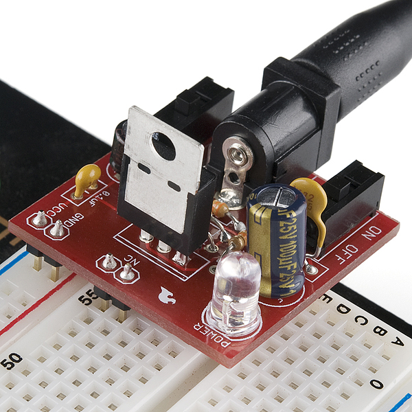
Breadboard Power Supply 5V/3.3V

Breadboard Power Supply 5V/3.3V - here's the link - https://www.sparkfun.com/products/114

And here's the spiel:

Breadboard Power Supply 5V/3.3V
PRT-00114 RoHS Compliant

Description: Here is a very simple breadboard power supply kit that takes power from a DC wall wart and outputs a selectable 5V or 3.3V regulated voltage. The .1" headers are mounted on the bottom of the PCB for simple insertion into a breadboard. Pins labeled VCC and GND plug directly into the power lines. The lone pair of pins have no electrical connection but help support the PCB.
There are two pins available within the barrel jack footprint. Any stripped +/- DC supply can be connected instead of the barrel connector. Board has both an On/Off switch and a voltage select switch (3.3V/5V).
Comes as a bag of parts kit and is easily assembled if you can follow the silkscreen indicators and have beginning experience with a soldering iron. You will need to read the resistor bands or use a multimeter to determine the resistor sizes.
Dimensions: 1.25x1.25"
Kit Includes:
  • DC Barrel Connector (2.1mm center positive)
  • TO-220 Voltage Regulator (LM317 1.5A max current)
  • 1N4004 Reverse Protection Diode
  • 100uF 25V Capacitor
  • 10uF 25V Capacitor
  • 0.1uF 50V Capacitor
  • Red Power LED - High Brightness
  • 2 x SPDT Slide Switch
  • 4 x 0.1" Header Pins
  • 2 x 330 Resistor 1/6W
  • 390 Resistor 1/6W
  • 240 Resistor 1/6W
  • Bare PCB with Silkscreen Indicators
  • PTC resettable fuse


The soldering was pretty straightforward. I used my wire cutters to split the 4 header pins into two. As I didn't have a vice to hold the board, I used a kind of manual solder and reflow to get a component as close/straight as I needed it by soldering one pin, then soldered the other pins. This was most necessary for the two switches and the header pins (because I couldn't actually bend those pins under the board to hold them in place - like I could with the resistors etc).

Soldering everything left me with a little problem. Er, my breadboard's not compatible with the stabalising (NC) pins!


Back to the 'soldering' board, remove the NC pins ...


Bingo! Provides 3.3V or 5V via a switch, making the LED brighter or dimmer.

The circuit uses an LM317 voltage regulator, and there is a good video tutorial about this component online [LM317 Adjustable Voltage Regulator Tutorial].

Raspberry Pi - BI-COLOR RIGHT ANGLE LED - 2xGPIO

Moving on from "My first GPIO LED", I decided to take a look at a different LED I had in my possession, an L-59BL/1.

This LED has 3 pins and I had no idea what they were for, so I Googled it and found this parts list, and this data sheet.

The interesting bits are in this diagram:


So this LED has two anodes, one for Red and one for Green. This would let me try and use two GPIO Pins.

I decided to leave the +5V LED connected, and so used another Female-to-Female jumper to connect Pin-12 (GPIO-18). This would be in addition to the already connected Pin-11 (GPIO-17).


Original image found here - http://www.raspberrypi-spy.co.uk/2012/06/simple-guide-to-the-rpi-gpio-header-and-pins/.

To connect one anode to the circuit, I decided to use the 3x10k-Ohm in parallel I already had to limit the current for Pin-11. But with the +5V LED taking up another resistor, that left me with no more resistors!

After some digging around, I found a 1k-Ohm SIL (similar to this) that I had removed from a previous PCB. I would use this for the second anode.

I stripped 3 Female-to-Female jumper wires off my ribbon cable to house the 3-Pin LED.

The finished circuit looks like this (the picture had to be taken in the dark as the LED was quite dim in my circuit).


To control GPIO-18, I had to follow the setup steps from my previous post.
root@raspberrypi:~# echo "18" > /sys/class/gpio/export
root@raspberrypi:~# echo "out" > /sys/class/gpio/gpio18/direction

Then I could control both lights.
root@raspberrypi:~# echo "1" > /sys/class/gpio/gpio17/value
root@raspberrypi:~# echo "0" > /sys/class/gpio/gpio17/value
root@raspberrypi:~# echo "1" > /sys/class/gpio/gpio18/value
root@raspberrypi:~# echo "1" > /sys/class/gpio/gpio17/value
root@raspberrypi:~# echo "0" > /sys/class/gpio/gpio17/value
root@raspberrypi:~# echo "0" > /sys/class/gpio/gpio18/value
root@raspberrypi:~# echo "1" > /sys/class/gpio/gpio17/value
root@raspberrypi:~# echo "0" > /sys/class/gpio/gpio17/value
root@raspberrypi:~# echo "1" > /sys/class/gpio/gpio18/value

I didn't actually get any Red light at all! I think this is because the part I have is actually a Yellow/Green two-colour part.

Saturday, 18 August 2012

Raspberry Pi - My first GPIO LED

Following the directions on these pages:

[1] http://elinux.org/RPi_Tutorial_EGHS:LED_output (Circuit 1 - Basic LED Driving Circuit)
[2] http://elinux.org/RPi_Low-level_peripherals#GPIO_Driving_Example_.28Shell_script.29

See this Simple Guide to the RPi GPIO Header and Pins page for how the Pi's Pin numbers map to the GPIO Pins. The guide's Pin diagram is shown below:


I will use Pin-11 on the Pi, which translates to GPIO-17. Therefore, I use GPIO-17 in the shell.
pi@raspberrypi ~ $ sudo -i
root@raspberrypi:~# echo "17" > /sys/class/gpio/export
root@raspberrypi:~# echo "out" > /sys/class/gpio/gpio17/direction
root@raspberrypi:~# echo "1" > /sys/class/gpio/gpio17/value
root@raspberrypi:~# echo "0" > /sys/class/gpio/gpio17/value

The following picture shows the setup.


The top Red-Rail is Pin-11 (GPIO-17) output. The bottom Red-Rail is Pin-2 (+5V). Both Blue-Rails are Pin-6 (GND).

There's an LED connected between Pin-2 (+5V) and Pin-6 (GND), in series with a 10k-Ohm resistor. This will always be On, and just proves that the Pi is supplying power.

There's an LED connected between Pin-11 (GPIO-17) and Pin-6 (GND), in series with a 10k-Ohm resistor.

The shell commands as specified above, will turn the LED On and Off.

In practice, the LED connected to 5V is brighter than the LED connected to GPIO-17. I assume this is because GPIO voltage levels are 3.3 V.

The GPIO-connected LED wasn't very bright. I think this is a combination of the lower voltage level (3.3V) and using a resistor value 37 times bigger than the 270-Ohm resistor recommended in [1].


To increase the brightness of the GPIO LED, I used 3x10k-Ohm resistors in parallel to decrease resistance to 3.3k-Ohm.

Sunday, 19 February 2012

Hello

This is where news of grimbodroid's applications will appear!